Steel Supply Co Home > Steel Products > Slide Bearings, Bearing Pads, and Neoprene > Slide Bearings
Slide Bearings
Sliding Bearings, also referred to as Expansion Bearings, Pipe Bearings, and Piping Supports
Specific Slide Bearing Compositions
Fluorogold® Slide Bearings
Teflon® Slide Bearings
Graphite Slide Bearings
Carbon Filled Teflon®/PTFE
Fluorogold® Recessed Slide Bearings
The SLIDE BEARING as differentiated from bridge bearings, elastomeric bearings, and other typical expansion bearings, transmits a vertical load from a supported structure to the sub-structure while providing for controlled horizontal movement. In its basic form, as shown below, it is not utilized as vibration dampener.
Horizontal movement is achieved with two independent members separated by a low coefficient of friction sliding surface, usually Fluorogold® or Teflon®. The Slide Bearing illustrations below show a typical slide bearing configuration:
FC-1010-CS 1/4L (click for more configurations)
FC indicates Fluorogold® as the sliding surface. 1010 indicates the thickness of each component. In this case 3/32” thick Fluorogold® bonded to 10 gauge steel. CS shows it will be carbon steel, as opposed to stainless steel, some type of Viblon, Neoprene or other material. 1/4L calls for the Fluorogold® to be set back 1/4” from the edge of the steel backing plate.


Notice in all three Slide Bearing illustrations the lower member has not moved. Figure 1 shows the bearing in its neutral position. The engineer or designer will have calculated the maximum distance the structure being supported will expand and contract, which will be referred to as “travel.” (Arrow in fig. 2 and 3) Also notice the upper member is larger than the lower. The object is the surface of the lower member is never exposed. This allows for a predictable, consistent area the vertical load transfers onto.
A second important reason the lower member is never exposed is to prevent sediment, debris, etc. from settling on the Fluorogold® or Teflon® surface. If embedded in the Fluorogold® surface this debris, under the pressure the Slide Bearing Assembly supports becomes an abrasive and will dramatically shorten the life of the bearing.
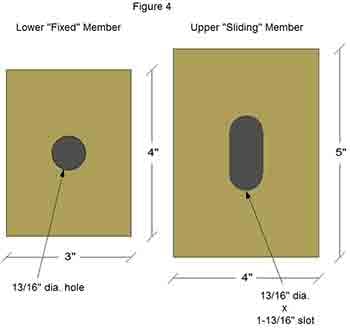
As the expansion and contraction within the Slide Bearing occur there will be some method of maintaining the correct position and not allowing the upper member to drift sideways as it travels. Often this is done with a structural bolt which acts as a dowel, Fig. 4
For the assembly to maintain a low coefficient of friction and the greatest potential durability it has to function between 70 and 2,000 psi. Ideally the design will be from 800 to 1,000 psi. This is controlled by the size of the lower Slide Bearing member.

Example;
In figure 4 the lower element is 3” x 4”. There is a hole the support/guide bolt will pass through. This does not figure in the psi calculation.
The Upper element is 4” x 5”. This is relevant only to the travel this bearing assembly will allow. It does not calculate into the psi this assembly will support. It has a slot, 13/16” x 1-13/16”. This does subtract from the psi load.
The equation in this case would be;
Lower Element – Upper Slot Slot Dimensions = Surface Area
(3” x 4”) - (13/16” x 1-13/16”) = Surface Area
The slot area calculates to 1.47256 sq. inches. Rounding the slot to 1.50” leaves a surface area of 10.50”
Therefore this bearing has a minimum load of 735 lbs. and a maximum of 21,000 lbs. Ideally, targeting the 800 to 1,000 psi range, it would be suited for a load of 8,400 lbs. to 10,500 lbs. This would leave ample leeway for fluctuations in the load during the life of the structure.
For more information on specific Slide Bearing systems click the individual link;
Fluorogold Slide Bearings / Teflon Slide Bearings / Graphite Slide Bearings
Return to Slide Bearings, Bearing Pads, and Neoprene
Follow the Steel Supply Co. on Social Media!
To learn more about Slide Bearings, Bearing Pads, and Neoprene, contact us or request a free quote today.


